prilicno sam u guzvi tako da evo copy/paste bitnog dela STM-ovog primera + po neki komentar od mene.. malo detaljnije sutra
konfiguracija
Code:
//dakle ova funkcija kao sto pise konfigurise EXTI interrapt
void EXTILine0_Config(void)
{
//GPIO struktura nam treba da bi konfigurisali PA0 pin
GPIO_InitTypeDef GPIO_InitStructure;
//NVIC struktura sluzi za siljenje vektora prekida
NVIC_InitTypeDef NVIC_InitStructure;
// EXTI definise EXTERNAL INTERRUPT
EXTI_InitTypeDef EXTI_InitStructure;
//dakle ovde kresnemo PORTA modul, tj damo mu clock
RCC_AHB1PeriphClockCmd(RCC_AHB1Periph_GPIOA, ENABLE);
//ovde kresnemo syscfk modul, tj damo mu klok,
//syscfg modul obradjuje external interrupt
RCC_APB2PeriphClockCmd(RCC_APB2Periph_SYSCFG, ENABLE);
//ovo je valjda jasno, dakle definisemo PA0 kao input
GPIO_InitStructure.GPIO_Mode = GPIO_Mode_IN;
GPIO_InitStructure.GPIO_PuPd = GPIO_PuPd_NOPULL;
GPIO_InitStructure.GPIO_Pin = GPIO_Pin_0;
GPIO_Init(GPIOA, &GPIO_InitStructure);
//ovde vezujemo PA0 na EXTI Line0
SYSCFG_EXTILineConfig(EXTI_PortSourceGPIOA, EXTI_PinSource0);
/* Configure EXTI Line0 */ //konfiguracija EXTI-a
EXTI_InitStructure.EXTI_Line = EXTI_Line0;
EXTI_InitStructure.EXTI_Mode = EXTI_Mode_Interrupt;
EXTI_InitStructure.EXTI_Trigger = EXTI_Trigger_Rising;
EXTI_InitStructure.EXTI_LineCmd = ENABLE;
EXTI_Init(&EXTI_InitStructure);
/* Enable and set EXTI Line0 Interrupt to the lowest priority */
//postavljanje prioriteta ovog interapta
NVIC_InitStructure.NVIC_IRQChannel = EXTI0_IRQn;
NVIC_InitStructure.NVIC_IRQChannelPreemptionPriority = 0x01;
NVIC_InitStructure.NVIC_IRQChannelSubPriority = 0x01;
NVIC_InitStructure.NVIC_IRQChannelCmd = ENABLE;
NVIC_Init(&NVIC_InitStructure);
}
i samo hendlanje interapta
Code:
void EXTI0_IRQHandler(void)
{
if(EXTI_GetITStatus(EXTI_Line0) != RESET)
{
// ovde uradi nesto
/* Clear the EXTI line 0 pending bit */
EXTI_ClearITPendingBit(EXTI_Line0);
}
}
Bitno:
Code:
External interrupt/event lines are mapped as following:
1- All available GPIO pins are connected to the 16 external
interrupt/event lines from EXTI0 to EXTI15.
2- EXTI line 16 is connected to the PVD Output
3- EXTI line 17 is connected to the RTC Alarm event
4- EXTI line 18 is connected to the USB OTG FS Wakeup from suspend event
5- EXTI line 19 is connected to the Ethernet Wakeup event
6- EXTI line 20 is connected to the USB OTG HS (configured in FS) Wakeup event
7- EXTI line 21 is connected to the RTC Tamper and Time Stamp events
8- EXTI line 22 is connected to the RTC Wakeup event
In order to use an I/O pin as an external interrupt source, follow steps below:
1- Configure the I/O in input mode using GPIO_Init()
2- Select the input source pin for the EXTI line using SYSCFG_EXTILineConfig()
3- Select the mode(interrupt, event) and configure the trigger
selection (Rising, falling or both) using EXTI_Init()
4- Configure NVIC IRQ channel mapped to the EXTI line using NVIC_Init()
@note SYSCFG APB clock must be enabled to get write access to SYSCFG_EXTICRx
registers using RCC_APB2PeriphClockCmd(RCC_APB2Periph_SYSCFG, ENABLE);
E sad, znam da ima dosta pitanja, veliki broj odgovora je ovde:
http://www.embedds.com/stm32-interrupts-and-programming-with-gcc/
(slicna/ista je prica i za M4)
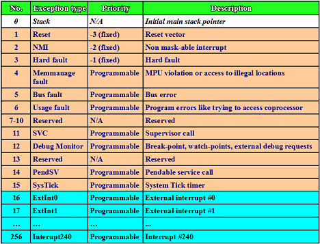
Citat:
ARM Cortex-M3 microcontrollers may have up to 256 interrupts sources. First 15 interrupt sources are called system exceptions. These exceptions rise within Cortex core like reset, NMI, hard fault and error, debug and SystTick timer interrupt. In the exception table they start from address 0×00000004 and are numbered from 1 to 15. There is no 0 number exception (FYI – the very top of exception table address is used to store starting point of stack pointer)
inace, pitanje "zasto se fnkcija zove bas tako", fora je sto biblioteka odradi sve oko setovanja vektora tako da postoji stm32f4xx_it.c u kome su prazne funkcije za sve interapte i onda samo unutra ubacis svoj kod ...


 STM32F4 - Interrupt-i